What Are the Typical Thicknesses of PCB Flex?
Typical Thicknesses of PCB Flex
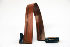
PCB flex is a very versatile material that can be used in a variety of electronic devices. Its flexibility allows it to be curved and folded into tight spaces where rigid boards cannot fit. Thinner flex circuits, however, are more prone to damage and are less durable than thicker circuits. The best thickness for a flex circuit depends on the intended use and environmental conditions.
The total thickness of a pcb flex depends on the number of copper layers and the thickness of the base insulating layer. Simple single-layer constructions with polyimide can be as thin as 1 mil, while double and multi-layer circuits require at least 2 layers of copper. The thickness of the copper layers also impacts the overall thickness, with thinner conductors requiring less insulation than thicker ones.
A flex circuit’s thickness can be adjusted by changing the thickness of the insulating layer or adding stiffeners. Thicker circuits can withstand greater stress than thinner circuits, making them more durable in dynamic flex applications and harsh environments. However, they may not be able to bend as tightly and could have higher current loads.
What Are the Typical Thicknesses of PCB Flex?
In addition to the circuit layer thickness, the thickness of the insulating materials is determined by the choice of adhesive and other layers. For example, acrylic adhesives are suitable for dynamic flex applications, while epoxy is more likely to be damaged by repeated bending.
When choosing a thickness for your pcb flex, consider the number of circuit layers, if it will be a static or dynamic board, and the environmental conditions the board will be subject to. A static board will flex only during installation and is unlikely to be bent afterward, while a dynamic board must be able to withstand tens of thousands of bends over its lifetime.
The minimum flex circuit thickness also depends on the design and size of the components. For example, a dense layout of fine pitch components might require a 5+ mil circuit, which can be achieved by using thicker materials such as Kapton or FR-4. Lastly, the type of solder used on the flex circuit can affect its thickness. Typically, lead-free solder is used for flex circuits as it is more environmentally friendly. This also helps prevent copper fatigue and corrosion over time.
The thickness of a PCB flex is mainly determined by the number and layer density of the copper foil. Thicker copper offers better current carrying capacity, resilience, and resistance to damage, but increases the overall thickness of the circuit. The thickness of the insulating dielectric also impacts the final thickness, with a thinner material offering lower cost but greater sensitivity to stress and environmental factors.
The thickness of the flex circuit can be further increased by the addition of components, shielding, and other layers. The addition of these elements can also make the flex circuit more durable, but at an additional cost. Ultimately, the thickness of the flex circuit should balance flexibility, durability, and manufacturing costs for the specific application.