How Quality Control Is Managed in PCB Circuit Board Assembly
Managed in PCB Circuit Board Assembly
As PCBs become increasingly complex, manufacturers have to employ several different tests and verifications to guarantee that they’re producing high-quality boards that function as intended. With so many components in such tiny packages, a single defect can undermine the entire product design and potentially torpedo the production run. This is why it’s crucial to choose an ECM that follows strict PCB assembly quality control methods and employs all necessary inspection processes.
To produce a quality PCB, the first step is to prepare the board for assembly by applying solder mask to all areas that will be soldered. This is important because it ensures that the solder will stick to the copper traces and planes on the surface of the board. It also prevents the board from absorbing moisture, which could damage it or cause it to function improperly.
Once the board has been masked and is ready for assembly, it’s sent to a fabrication facility to be made into a bare circuit board. This process includes etching all of the traces and planes on the board, compressing the metal layers together, and then adding the other components. After that, the finished product is inspected and tested to make sure it functions properly and meets industry standards.
How Quality Control Is Managed in PCB Circuit Board Assembly
The most common method of inspecting a pcb circuit board assembly is visual inspection. This involves someone closely examining each component to make sure that it fits where it needs to and that all connections are secure. Ideally, this person should be able to spot any potential issues by looking at the board under a bright light and viewing it from all directions. This is a time-consuming and labor-intensive process, but it’s one of the most effective ways to catch any mistakes early on in the production cycle.
Automated optical inspection is another popular way to check for quality during PCB assembly. This uses a series of cameras arranged at various angles to view the PCB and compare it to a detailed schematic. If there are any differences between the two, the machine will flag the board and alert a technician so that the issue can be addressed.
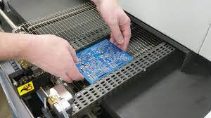
Lastly, some PCBs are checked with X-rays to look for hidden problems that might not be visible with the naked eye. This is a more invasive technique, but it’s helpful for checking for things like voids, blobs of solder that aren’t connected to their respective terminals, and misplaced components. The X-ray results are then used to determine the fate of the board, which might be sent back for rework or scrapped entirely, depending on the company’s quality control standards.
There are also other testing processes for a PCB, including the bed of nails test and flying probe tests, that can help detect open and short circuits on critical nets. These electrical tests are typically done after the board is fabricated, but they can also be performed during the assembly process if needed. The goal of any quality inspection program is to catch errors as soon as possible, which will help prevent them from impacting the final products that customers buy and use.